Vera Rubin Decoded Pt. 4 | Rack Assembly - Trays, PCB, and Cooling
Where to Read What — Series Map
| Part | Title | Scope |
|---|---|---|
| 1 | Platform Framing & Architecture Map | Blackwell → Rubin platform thesis, headline specs |
| 2 | Rubin GPU — Engineering Deep Dive | Process node, SMs, HBM4, NVLink-C2C, package, CPX + Groq 3 LPX |
| 3 | Vera CPU & the Networking Silicon Family | Vera CPU, NVLink 6 Switch, ConnectX-9, BlueField-4, Spectrum-6 |
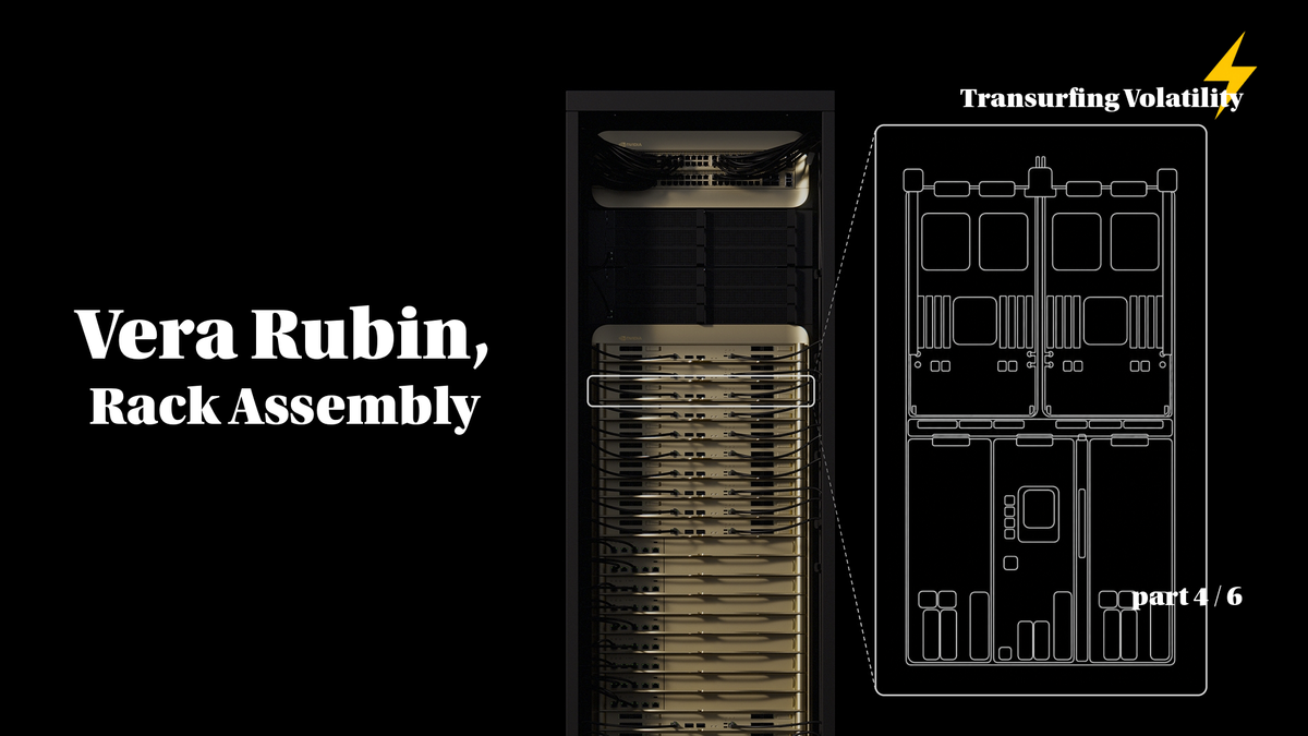
| 4 | Rack Assembly — Trays, PCB, and Cooling (this part) | HGX vs NVL72, compute tray modules, cableless midplane, PCB upgrade, liquid cooling |
| 5 | Rack Power and the Networking Fabric | Power delivery, HVDC, tray↔rack wiring, scale-up NVLink 6, scale-out InfiniBand + Ethernet |
| 6 | Supply Chain — Master Reference | Suppliers by subsystem across the entire stack |
1. From Chips to Tray to Rack — Assembly
Now that the individual chips are covered, the next question is how they get put together. The six chips don't ship as a loose box — they're integrated into a layered assembly hierarchy:
Hierarchy: chip → module → compute tray → rack → SuperPOD
- Chip — individual silicon (Rubin GPU, Vera CPU, etc.)
- Module — a small PCB that carries one or more chips with their immediate support (memory sockets, VRMs, connectors)
- Compute tray — a 1U chassis containing several modules wired together via a midplane
- Rack — 19-inch cabinet containing 18 compute trays + 9 NVLink switch trays + 4 power shelves
- SuperPOD — multiple racks connected via Spectrum-6 Ethernet (covered in section 8)
This section walks through the compute tray's six internal modules, how they connect, how they're cooled and powered, and how 18 of them combine into one NVL72 rack.
(1) Anatomy of One VR NVL72 Rack
The headline numbers Nvidia advertises (72 GPUs, etc.) come from a simple multiplication:
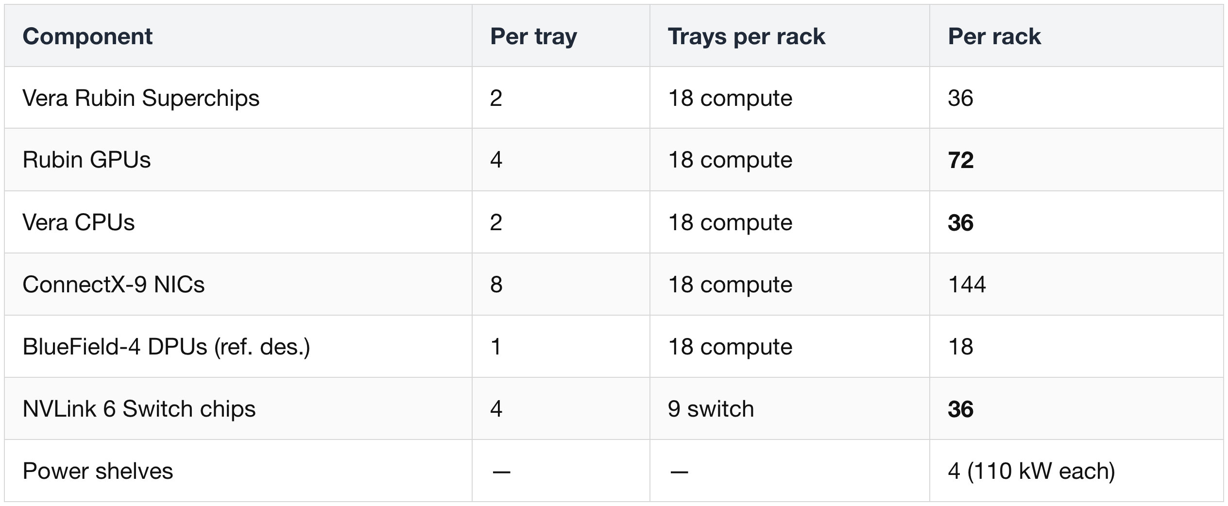
A "Vera Rubin Superchip" is 1 Vera CPU + 2 Rubin GPUs linked over NVLink-C2C on a single Strata module. Two superchips per tray, 18 trays per rack — that's the math behind the 72-GPU figure.
The original naming was actually "VR NVL144" because Nvidia briefly counted GPU dies (2 reticle-sized dies per Rubin package × 72 packages = 144 dies). Nvidia switched back to "NVL72" in December 2025 to count packages — that's the number displayed today.
(2) HGX Rubin NVL8 — Alternative Form Factor
Before going deeper into the NVL72 tray internals, it's worth noting that Rubin ships in two deployment form factors that reflect two opposite Nvidia design philosophies — DGX (turnkey integrated appliance) and HGX (modular GPU tray for OEM customization).
This part will mainly cover the rack-scale VR NVL72, which is a DGX-style product. The alternative is HGX Rubin NVL8 — a chassis-scale server (8 GPUs) that continues the GB300 → HGX B300 lineage. Everything from § 3 onward focuses on NVL72; this is the one section where HGX appears.
1) DGX vs HGX — Two Design Philosophies
DGX and HGX express opposite design philosophies at the hardware level. Knowing which one a Nvidia GPU product follows tells you most of what you need to know about its customization story.
DGX — Turnkey AI Appliance
- Fixed, fully integrated node: predefined GPU count, NVLink topology, CPU, memory, networking, and software stack — all tuned as a single system by Nvidia.
- Vendor-managed integration: Nvidia defines the full hardware + software stack; DGX partners ship the system "as is" with minimal configuration choice.
- Goal: reduce integration friction for customers. You buy a ready-to-run AI supercomputer, not a parts pile.
- Rubin-generation examples: DGX Vera Rubin NVL72 rack, DGX SuperPOD built from those racks.
HGX — Modular GPU Building Block
- Reference GPU tray + reference design: Nvidia ships a modular GPU tray (4× or 8× SXM Rubin GPUs) plus a reference architecture. OEMs slot that tray into their own chassis.
- OEM and cloud customization: OEMs (Dell, HPE, Lenovo, Supermicro) choose their own CPU (AMD or Intel), RAM, storage, network fabric (Spectrum-X, InfiniBand, or third-party), and management stack around the same HGX GPU tray.
- Goal: scale Nvidia GPUs inside custom-designed servers and hyperscaler racks — not just Nvidia-branded appliances.
- Rubin-generation examples: HGX Rubin NVL8 server (the focus of this section).
One-line summary
- DGX says: "This is a complete, Nvidia-integrated AI node. Take it as designed."
- HGX says: "Here's a standard GPU tray. Build your own system around it."
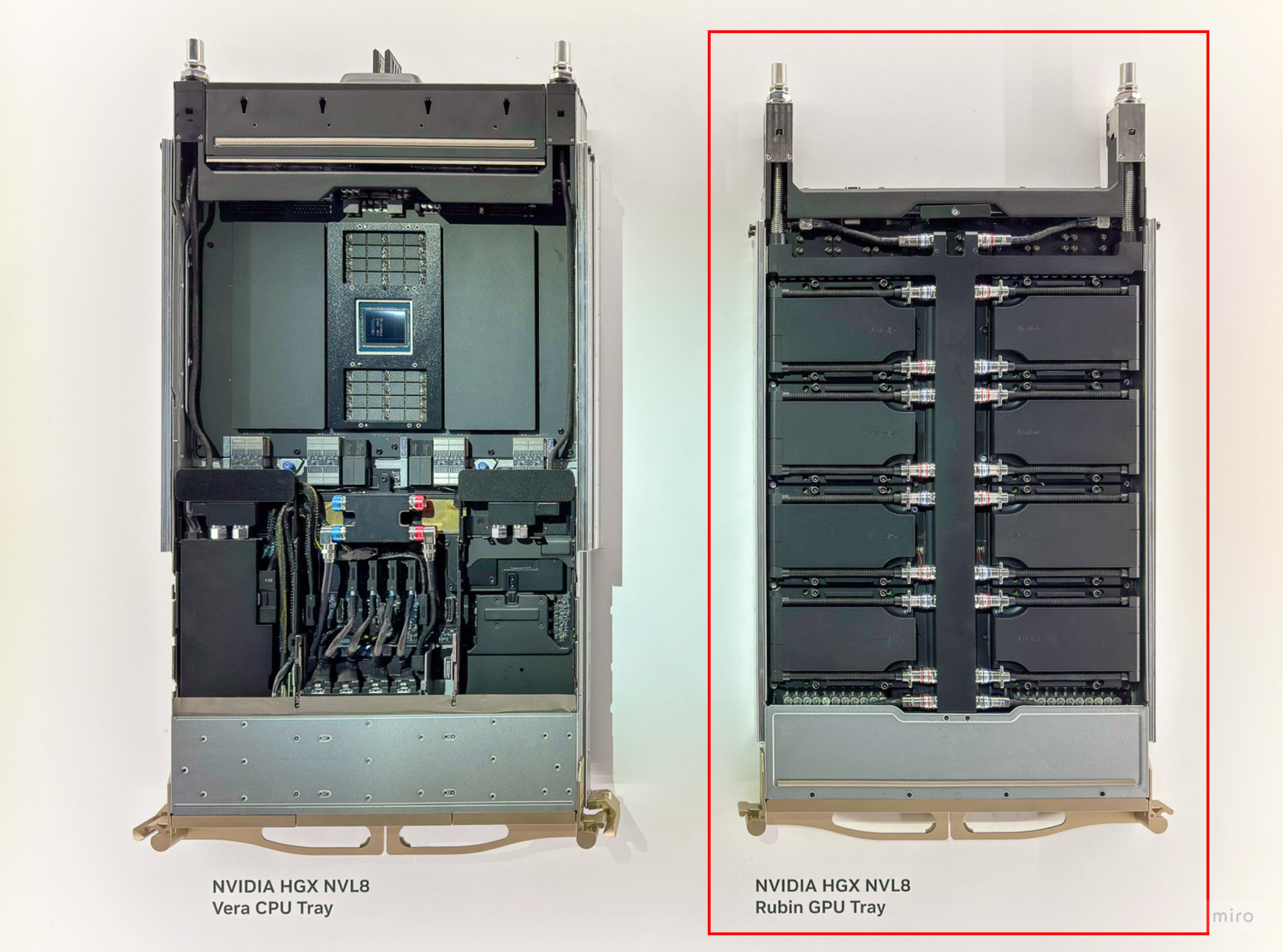
2) Form-Factor Contrast — Tray-Level vs Rack-Level
The most meaningful apples-to-apples comparison is at the tray level — HGX Rubin NVL8 (a complete chassis) vs a VR NVL72 compute tray (one 1U tray inside the rack). The rightmost column shows the full NVL72 rack for completeness:
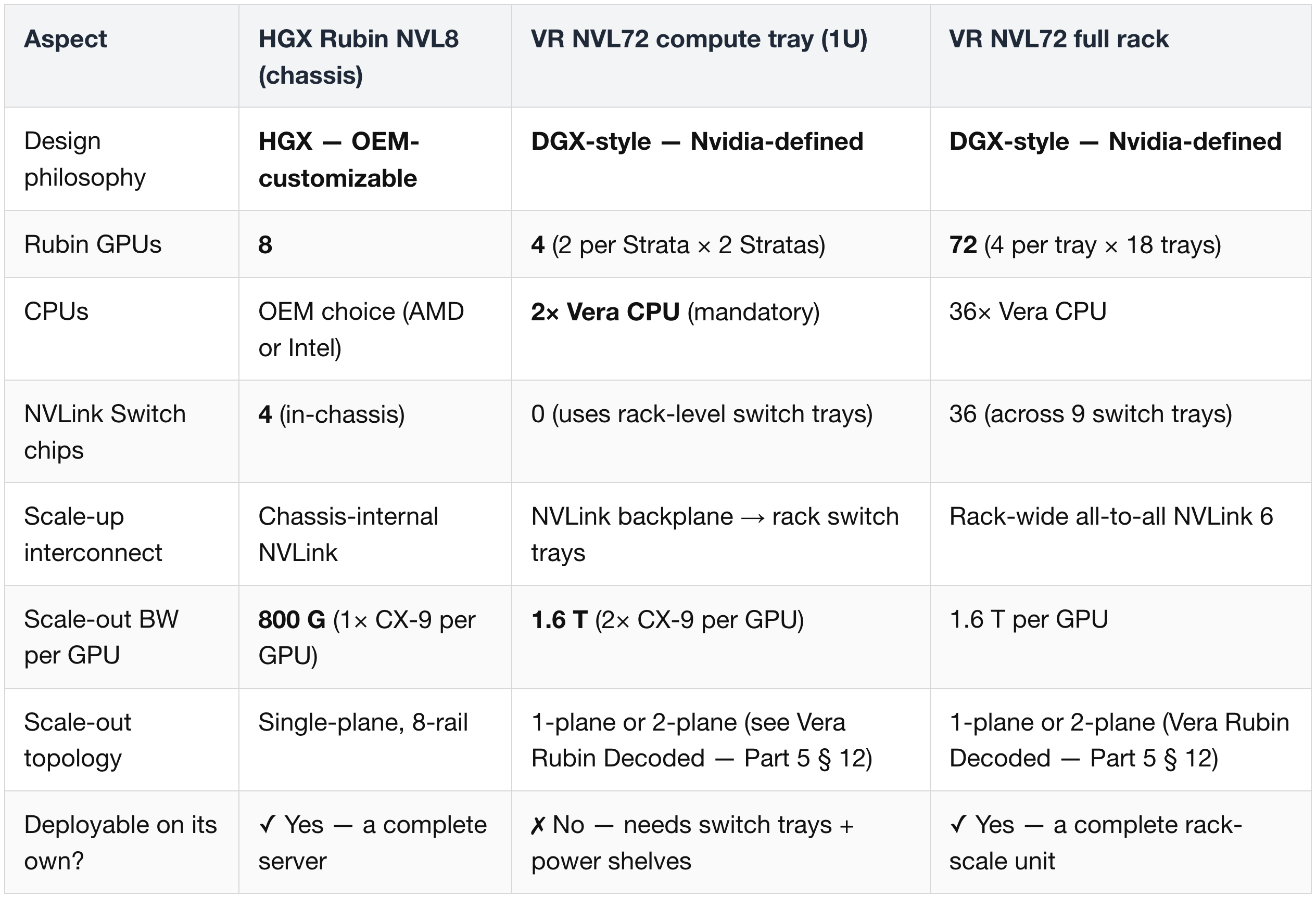
Reading the table:
- HGX NVL8 and a VR NVL72 compute tray sit at similar physical scale (server chassis ≈ 1U tray) but represent opposite ends of the customization spectrum.
- HGX NVL8 is the complete deployable unit. The NVL72 compute tray is one slice of a larger rack-scale design — it cannot run standalone.
- This is why the meaningful deployment-level comparison is HGX NVL8 ↔ NVL72 rack, but the meaningful architectural comparison is HGX NVL8 ↔ NVL72 compute tray.
3) How NVL72 Reaches 1.6 T per GPU Without a Faster NIC
- NVL72 does not use a literal 1.6T NIC silicon.
- Instead, two 800G CX-9 packages per GPU both connect to the paired Vera CPU via PCIe Gen6 lanes.
- The result is a "1.6T NIC" logically — same CX-9 silicon as HGX, just deployed at 2× density per GPU.
4) Adoption Patterns — Neoclouds vs Hyperscalers
Which companies pick which form factor follows a clear directional pattern. It's a tendency, not a hard rule.
Neoclouds → tend toward DGX (VR NVL72)
- Players: CoreWeave, Nebius, Lambda, Crusoe, TensorWave.
- Business model: GPU-as-a-Service — they are "GPU landlords" optimizing for speed of deployment and GPU utilization.
- Why DGX fits: turnkey rack-scale systems with pre-optimized Nvidia software stacks reduce integration time. Neoclouds want to spin up thousands of GPUs quickly without taking on custom-server engineering risk.
- Demand pattern: GPU count, TCO, and uptime matter more than custom topology. A standardized DGX node "just works".
Hyperscalers → tend toward HGX
- Players: AWS, GCP, Microsoft Azure, Meta (and, in practice, xAI for parts of its fleet).
- Business model: massive in-house-customized datacenter fabrics, with internal teams engineering custom servers, chassis, networking, and rack designs.
- Why HGX fits: lets them pair the Rubin GPU tray with their own choice of CPU (in-house ARM, AMD, or Intel), firmware, telemetry, NICs, power delivery, and orchestration. The HGX tray slots into their existing custom-rack architecture rather than forcing a Nvidia-branded box.
- Demand pattern: flexibility, scale, and homogeneous integration across millions of servers matters more than out-of-the-box turnkey speed.
Mixed deployments are also common
- A neocloud might run DGX racks for training tiers (fast deploy, high reliability) and HGX for inference tiers (cheaper, more customizable).
- A hyperscaler might keep most of its fleet on HGX but buy a small number of DGX racks for internal AI labs or strategic customers.
5) Why HGX Still Exists Alongside NVL72
- HGX targets smaller, more flexible deployments where rack-scale NVL72 is overkill — enterprise clusters, mixed-workload servers, lab-scale infrastructure, plus any hyperscaler that wants to integrate Rubin GPUs into its in-house chassis.
- HGX is single-plane, 8-rail — its topology hits the 1-plane formula ceiling (93,312 GPUs). HGX clusters are typically built at much smaller scale anyway, since the 8-GPU chassis granularity makes very large clusters operationally awkward.
- NVL72's 2× 800G logical port arrangement is what unlocks the 2-plane scale-out math covered in Vera Rubin Decoded — Part 5 § 12.
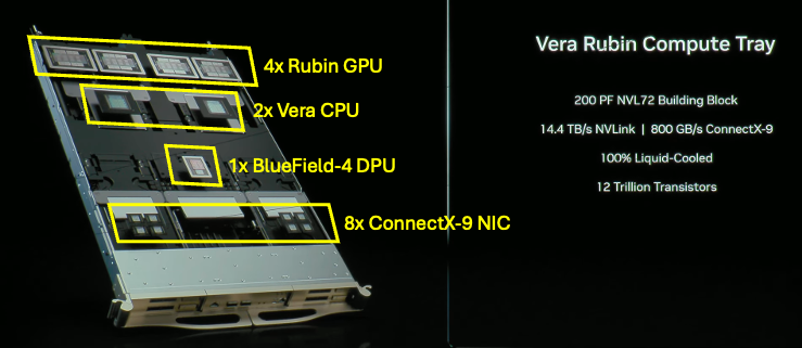
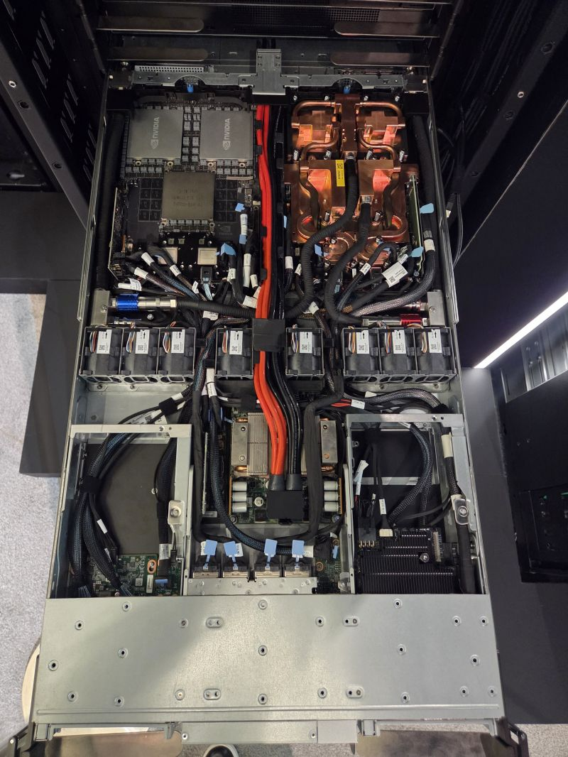
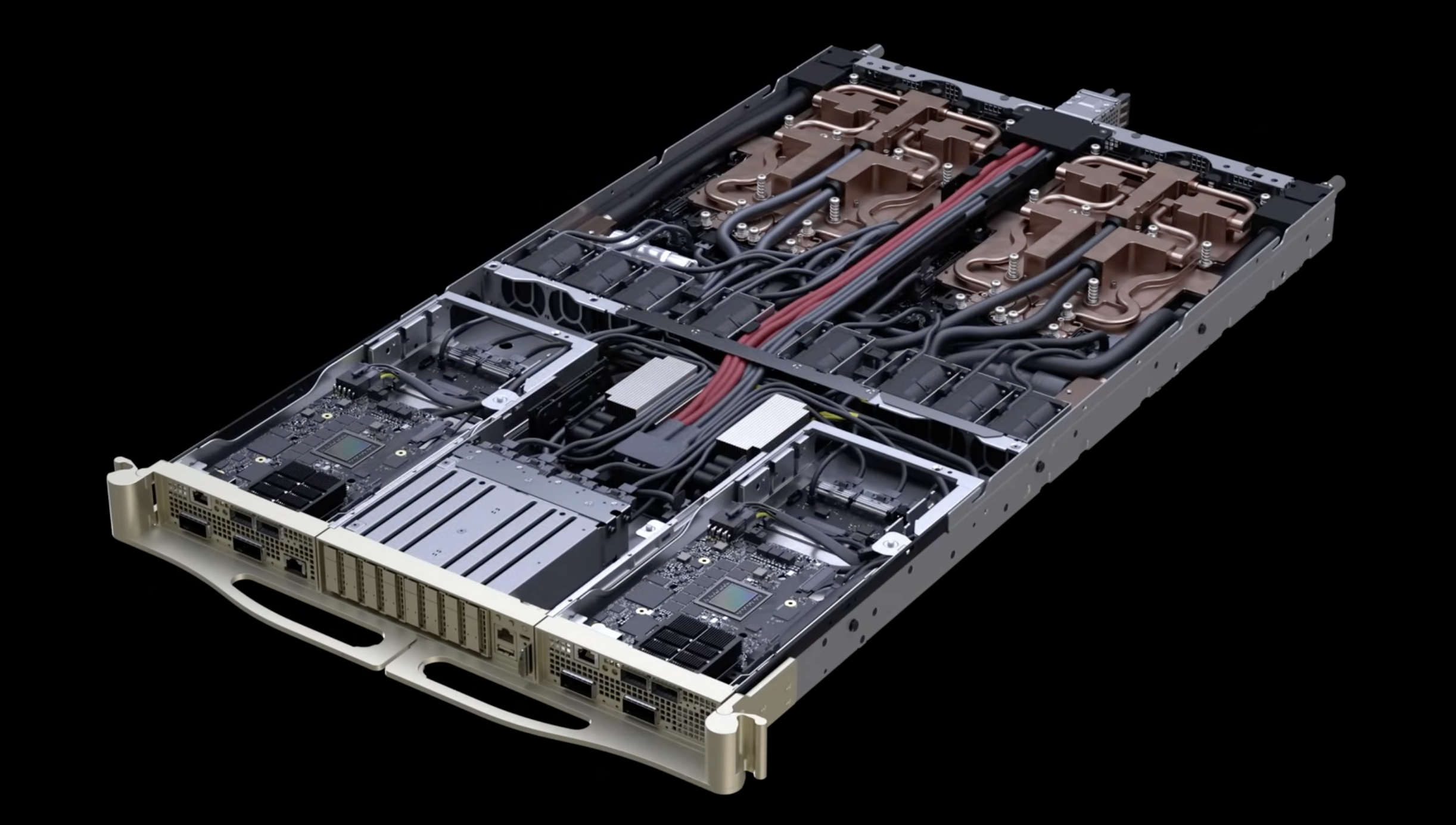
(3) The VR NVL72 Compute Tray — Six Modules
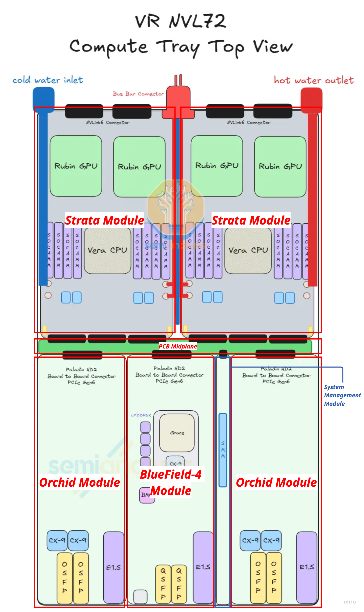
Each compute tray is a modular assembly of six module types, totalling 10 physical modules (2× Strata + 4× Orchid + 1× each of the rest). Reading the tray from back to front:
Strata Module ×2 (back of chassis)
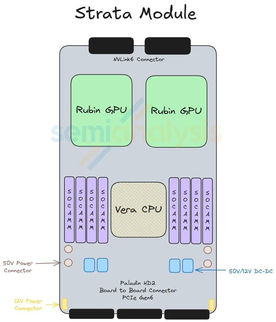
- What it carries: 1× Vera Rubin Superchip = 2× Rubin GPU + 1× Vera CPU + 8× SOCAMM sockets (LPDDR5X, 128 GB or 192 GB each)
- Power: 50 V direct from rack busbar; stepped down on-board to 12 V → 1 V (Strata draws ~4,800 W)
- Back-side connection: Paladin HD2 backplane connectors → NVLink 6 backplane → NVLink Switch Trays
- Front-side connection: Paladin HD2 board-to-board connectors → Midplane → front-half modules
- This module is the equivalent of the Bianca board from GB200/GB300, but redesigned: the CX-9 NICs that used to sit on Bianca have been moved forward into the Orchid modules.
Orchid Module ×4 (front of chassis)
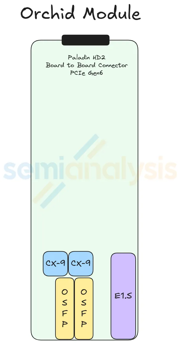
- What it carries: 2× ConnectX-9 NICs + 2× 800G OSFP cages + 1× E1.S NVMe SSD slot
- Layout: 2 Orchids stacked top-and-bottom occupy the front-left of the chassis; the other 2 stack on the front-right (each pair shares one cold-plate pair)
- Why moved to the front: the high-speed 200G Ethernet/InfiniBand signal from CX-9 needs to be short to reach the OSFP cages with low signal loss. The lower-speed PCIe Gen6 signal (which connects back to the Strata) is allowed to be longer because it's more tolerant of PCB-trace loss.
- Connection: Paladin HD2 connector → Midplane → Strata (PCIe Gen6 path)
Midplane ×1 (middle of chassis, vertical)
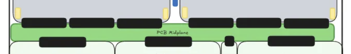
- What it is: a vertical PCB board sitting between the back half (Strata) and front half (Orchid + BF-4 + PDB + SMM) of the chassis
- What it does: routes PCIe Gen6 signals between the two halves of the tray via Paladin HD2 board-to-board connectors on both sides
- Why it exists: this is the new component that enables the cableless design — previously, GB200/GB300 used flyover cables here
- The Strata modules connect to one side of the midplane; the Orchid + BF-4 + PDB + SMM modules connect to the other side
BlueField-4 Module ×1 (front-center)
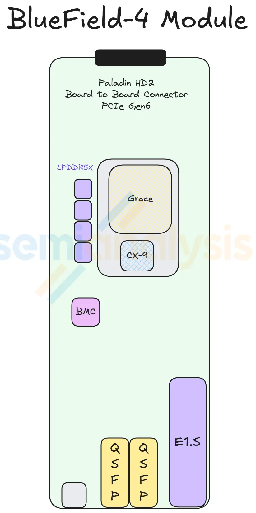
- What it carries: 1× BF-4 DPU + 128 GB on-board LPDDR5X + 512 GB pluggable SSD + AST2600 BMC
- What it does: runs the infrastructure plane (front-end networking, storage offload, security)
- Note: the most commonly customized slot — most hyperscalers replace BF-4 with their in-house DPU or simply a bare CX-9
Power Delivery Module ×1 (front-center, above BF-4)
- What it does: receives 50 V from the internal busbar cable, steps it down to 12 V via a modular power brick
- Distribution: 12 V then feeds the Orchid, BF-4, and SMM modules via smaller internal busbars
- Strata modules bypass the PDB entirely — they take 50 V directly and step it down on-board (because they draw too much current for centralized 12 V distribution)
System Management Module ×1 (front-center, below BF-4)
- What it carries: three smaller modules:
- SMM (System Management Module)
- TPM (Trusted Platform Module)
- DC-SCM (Datacenter Secure Control Module)
- What it does: management, security, BMC functions
- Customization: like BF-4 and PDB, this is one of three modules Nvidia allows hyperscalers to customize. Most hyperscalers ship their own design.
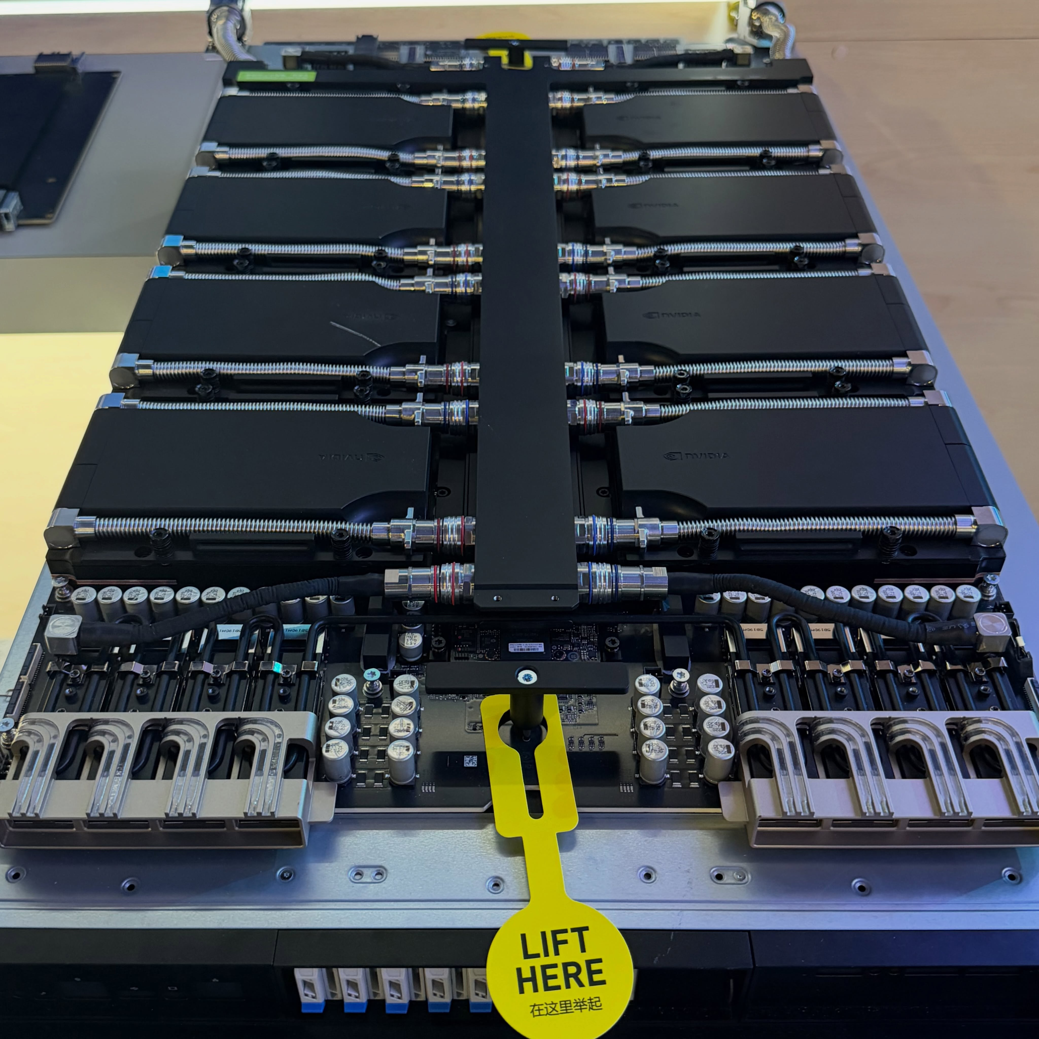
(4) Cableless Design — Why the Midplane Matters
The big mechanical change in VR NVL72 is going cableless inside the tray.
GB200/GB300 used flyover cables (DensiLink OverPass cables from Amphenol) to carry Ethernet and PCIe signals between modules. Those cables had two problems:
- Cable termination is fragile — easily damaged during assembly, the #1 failure point of GB200/GB300 assembly
- Routing space is scarce — the chassis is very dense, leaving little room for cable management
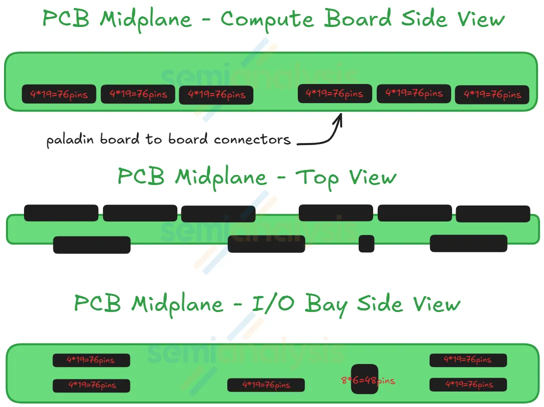
VR NVL72's answer: replace internal cables with Paladin HD2 board-to-board connectors and a midplane PCB.
How the cableless path works:
- Modules connect to the Midplane via Amphenol's Paladin HD2 connectors (not cables)
- Midplane carries PCIe Gen6 signals across the chassis (a relatively long ~500 mm trace from Strata to front-of-tray)
- PCB material upgraded (M7/M8 → M8/M9 CCL, HVLP2 → HVLP4 copper foil, possibly Quartz glass cloth) to reduce signal loss enough that PCIe Gen6 can run the full midplane length
- The faster 200G Ethernet/InfiniBand signal — too lossy for long PCB traces — is now confined to the short distance between CX-9 (on Orchid) and the front-panel OSFP cages
Result claimed by Nvidia (Jensen at CES 2026): compute tray assembly time drops from 2 hours → 5 minutes, an 18× improvement.
(5) PCB Material Upgrade — What the Cableless Design Forces
The cableless design has a downstream cost: PCIe Gen6 signals now have to travel ~500 mm of PCB trace from the Strata at the back of the tray, across the midplane, all the way to the Orchid module at the front. That's far enough that the PCB has to be made out of much higher-grade material than what GB200/GB300 used.
Why high-speed signals lose energy on PCB
Three loss mechanisms dominate at PCIe Gen6 speeds (64 Gbit/s per lane):
- Conductor loss (skin effect + surface roughness). At high frequency, current crowds toward the surface of the copper trace (the "skin effect"). If the copper surface is rough, the current path zig-zags, increasing resistance and energy loss as heat.
- Dielectric loss. The signal propagates partly as an electromagnetic wave whose electric field extends into the dielectric material (the resin + glass-fiber cloth between copper traces). The dielectric absorbs some of that energy. This loss scales with frequency, making it the dominant limiter for long PCB traces at modern signal rates.
- Geometry loss. Abrupt structures like vias and layer transitions act like bumps in a highway — they reflect a portion of the signal backward, increasing insertion loss.
Materials upgrade summary
The table below shows the CCL grade jump from Blackwell to Rubin (CCL = Copper Clad Laminate, the substrate material PCBs are built from):
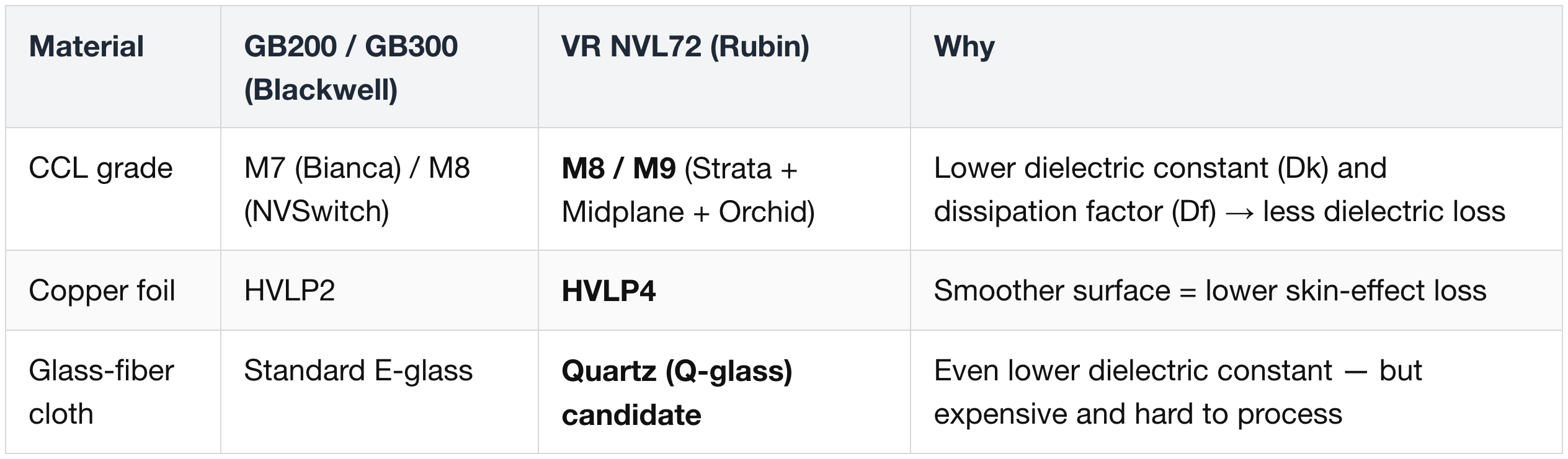
The CCL grades are indexed against Panasonic's Megtron series ("M7", "M8", "M9" = matches the dielectric constant + dissipation factor of Megtron 7/8/9). Panasonic effectively set the industry standard for high-end CCL.
HVLP (Hyper Very Low Profile) is a classification of copper foil surface roughness. Higher HVLP number = smoother foil = less conductor loss at high frequency. Suppliers like Mitsui Mining & Smelting, Furukawa Electric, and Circuit Foil Luxembourg make the high-grade foil used here.
Quartz glass cloth — adopted, then maybe walked back
- Quartz cloth (Q glass) is the next-generation reinforcing material that replaces standard glass fiber in CCL. It pushes the dielectric constant lower than any glass fiber, and is mechanically stronger with better thermal stability.
- Trade-off: Q glass costs multiples more than the highest-grade standard glass fiber, and is harder to process at the PCB manufacturing level — yields suffer.
- Initial Rubin plan was to use Q glass for the Orchid board and the Midplane — the two boards carrying the longest PCIe Gen6 traces.
- Current direction: Nvidia is exploring downgrading back to standard glass-fiber cloth on those boards if the signal integrity holds. Final decision is pending qualification data.
Why total PCB content grows ~2.3×
GB200/GB300 only had two boards with high-end material — the Bianca board (M7) and the NVSwitch board (M8). The front half of the GB200/300 compute tray didn't carry premium PCB.
VR NVL72 covers the front half of the chassis with high-end material too — the Orchid board and the Midplane are now both M8/M9-grade. Combined with the larger Strata board (replacing Bianca) and the various peripheral boards, the high-end PCB area grows ~2.3× from GB300 to VR NVL72. The Orchid board is the largest single contributor to that delta.
This translates directly into supplier dollar content for the PCB ecosystem (TUC, Iteq, EMC, Panasonic, Doosan on CCL; the PCB fabricators downstream of them).
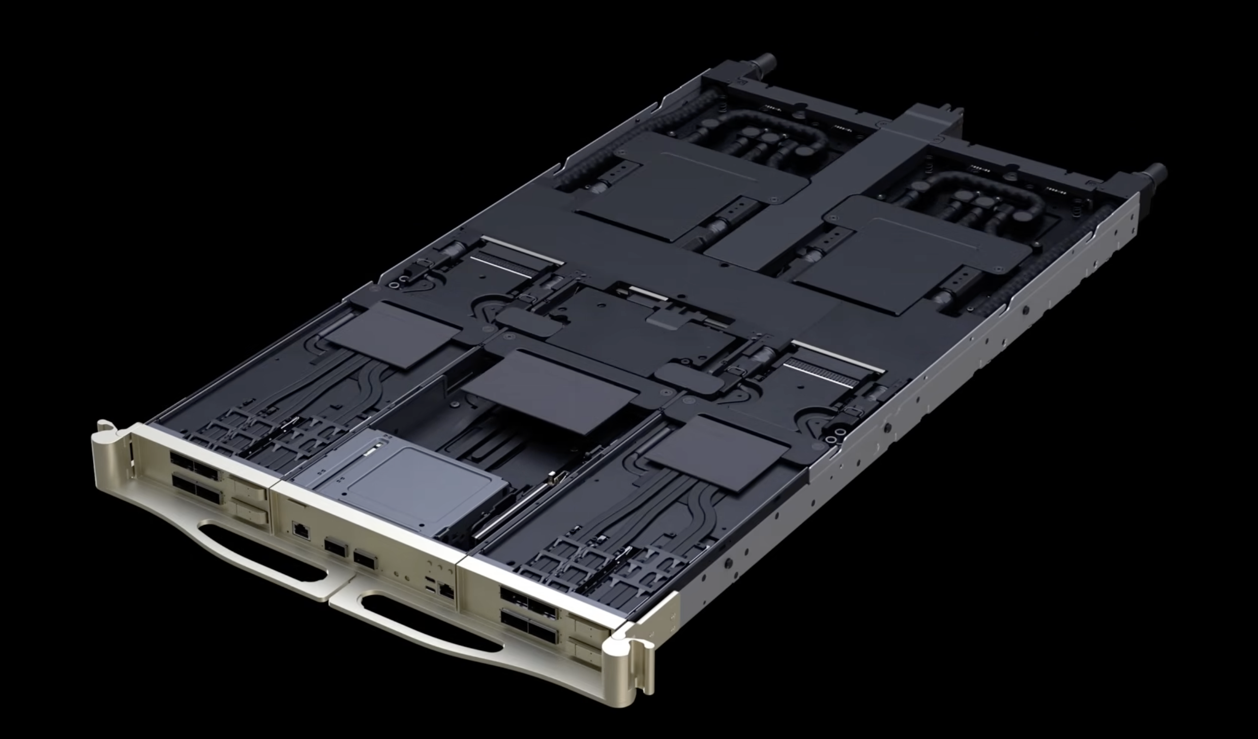
(6) Cooling — 100% Liquid, No Fans in the Tray
GB200/GB300 trays were ~85% liquid-cooled + ~15% air-cooled (small fans for the front-of-tray modules).
- While this enhanced targeted heat dissipation,
- it led to a surge in the number of adapters and minifolds, significantly increasing the risk of liquid leakage.
VR NVL72 goes 100% liquid-cooled — there are no fans inside the compute tray.
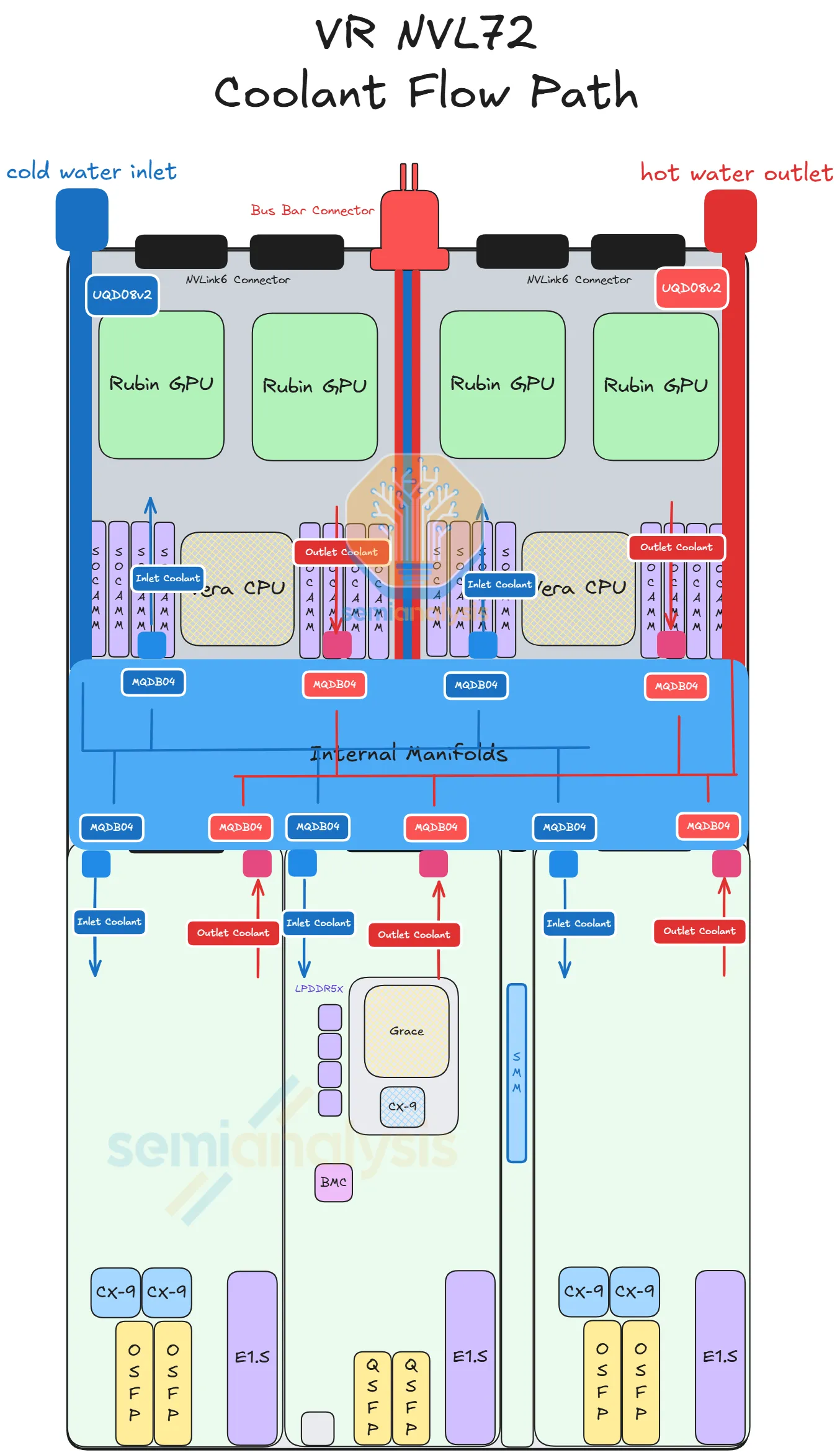
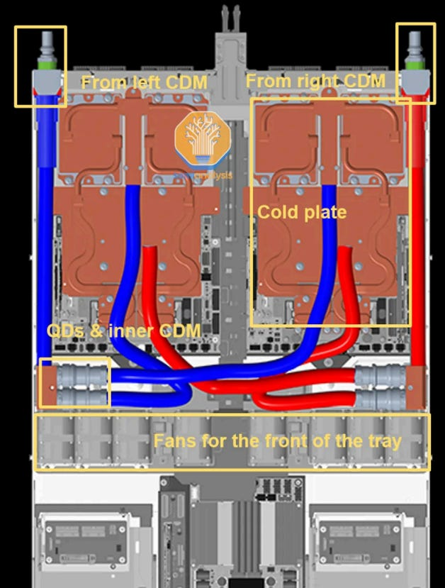
How it works:
- Coolant enters the tray via a UQD (Universal Quick Disconnect) on the back-left of the chassis
- An internal manifold sits in the middle of the chassis and distributes coolant to each module's cold plate
- Each module has its own cold-plate module (Strata, Orchid, BF-4, PDB, SMM)
- Each cold plate connects to the internal manifold via MQD (Mini Quick Disconnect — Nvidia's compact form factor)
- Coolant exits via another UQD on the back-right
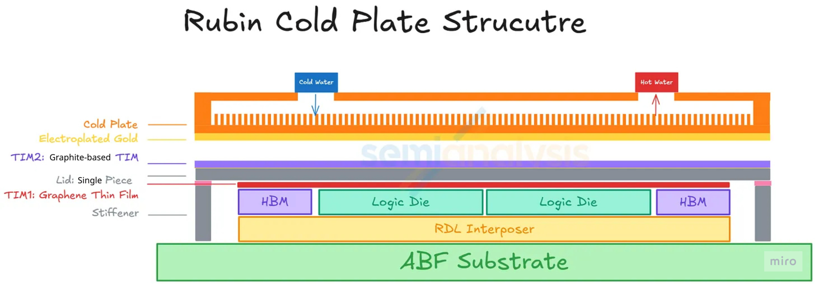
Cold-plate design on Rubin — what changed and what didn't
- Micro-channel cold plate (MCCP) — kept. The Rubin GPU cold plate uses MCCP with channel pitch reduced from 150 µm to 100 µm, increasing the surface area available for heat transfer. This upgrade is independent of the TIM2 choice and survives in the production design.
- Gold-plating layer on the cold-plate face — kept. The cold-plate face contacting the Rubin GPU's lid retains its electroplated gold layer in the final design. The layer was originally specced as a corrosion barrier against the liquid-metal Indium TIM2 (because indium and gallium alloys attack copper and form brittle intermetallics), and Nvidia kept the cold-plate-side coating in place even after TIM2 was switched to graphite — partly as an existing-process carry-over, partly for ongoing interface protection at the liquid-cooled side.
- Lid (package-side) gold plating — dropped. This is the change documented in Part 2 § 3 (7): the gold layer on the lid surface is removed in the final design, because its sole purpose was the liquid-metal barrier on the package side, which is no longer needed once TIM2 switched to graphite.
- TIM2 stack — graphite, not liquid metal. The interface between the lid and the cold plate is now a graphite-based TIM (typically a thin pyrolytic graphite or graphite-composite sheet) — mechanically stable, no flow or wicking, no metal corrosion, and with high enough thermal conductivity to handle Rubin's 2,300 W without the engineering risk of liquid metal.
Net effect on the cold plate: the MCCP body and the gold-plated face both carry over from the original plan. The change in the final design is on the package side — the lid no longer carries a gold coating, and the cold plate now sees a solid graphite sheet on its top face instead of a liquid-metal alloy.
Inlet temperature: up to 45 °C ("warm-water cooling"). This isn't unique to Rubin — Blackwell already supported >40 °C inlets — but Rubin officially extends it. Operating at 45 °C inlet potentially lets the datacenter skip mechanical chillers, lowering operating cost.
(7) Rack-Level Cooling — 45 °C Warm-Water and the Chiller-less Path
The compute tray is 100% liquid-cooled internally, but the actual heat still has to get out of the datacenter. That's where the rack-to-facility cooling loop matters — and it's where Rubin pushes hardest.
Warm-water cooling — what 45 °C actually means
Liquid cooling systems are characterized by the inlet temperature of coolant entering the rack. Lower inlet = colder coolant = easier to absorb heat, but it requires more facility-side energy to keep the coolant cold (usually via mechanical chillers).
- Traditional datacenters supplied coolant at 20–30 °C.
- "Warm-water cooling" pushes the inlet to 40 °C or higher — close to ambient air temperature in many climates, which means mechanical chillers can be skipped entirely and the heat is rejected with dry coolers or evaporative towers instead.
- Vera Rubin officially supports up to 45 °C inlet. This isn't actually new for the industry — Supermicro's DLC-2 system already supports >40 °C inlets on Blackwell, and Lenovo (Neptune liquid solution) and HPE have publicly discussed 100% liquid-cooled architectures at 45 °C since early 2025. Firmus has already removed chillers from GB200 deployments. What Rubin does is make this the official Nvidia operating envelope.
The delta-T trade-off
The catch with warmer inlets:
- Maximum outlet temperature (the system's ceiling) is around 65 °C in Blackwell reference designs (e.g., Vertiv's GB200 NVL72 reference design). Nvidia is expected to support similar ~65 °C return temperatures on Rubin.
- If inlet rises to 45 °C and outlet ceiling stays at 65 °C, the delta-T tightens from ~40 °C (for 25 °C inlet) to ~20 °C.
- A tighter delta-T means you need more coolant flow to move the same amount of heat. Specifically: Rubin moves roughly 2× the heat of Blackwell, and Nvidia indicates roughly 2.0–2.5× higher flow rate is required.
Pressure envelope
Pressure stays in line with the OCP MGX rack-level liquid-cooling spec:
- Maximum operating pressure: 72 psig (5 bar)
- Minimum burst pressure: 217 psig (15 bar)
- This means the existing pipes, quick-disconnects, and manifolds can carry over from GB200 mechanically — only the flow-rate handling has to scale.
Why hardware vendors win or lose here
- CDU (Coolant Distribution Unit) sizing. Current CDUs support ~10 GB200 racks each. With Rubin generating ~2× heat per rack, either (a) the same CDU supports fewer racks, or (b) CDUs themselves have to grow. Industry direction is the latter — moving from ~2 MW in-row CDUs today toward 3–6 MW facility CDUs. Delta, Schneider Electric, Vertiv, and nVent lead the CDU specialist segment; Foxconn and Quanta dominate the integrator role.
- Larger Quick Disconnects (QDs). Current 1-inch UQDs are being replaced by 2-inch QDs to handle the higher flow without pressure issues. Colder Products Company (CPC), Danfoss, Stäubli, and Parker Hannifin make these.
- Cold plates with finer micro-channels (MCCP) and gold-plated face. Gold plating on the cold-plate-side face carries over from the original plan (only the lid-side gold layer was dropped — see § 6 above). Suppliers like AVC, Delta, Boyd, CoolIT, and Auras are the relevant names.
- Larger pumps. Pump sizing is directly proportional to power density. Even motor-component suppliers like Allegro MicroSystems see content growth as larger or more numerous pumps are needed.
Dual-loop facility architecture (Schneider GB300 RD111 example)
A common deployment pattern (illustrated by Schneider Electric's GB300 Reference Design 111, published September 2025) is a dual-loop architecture:
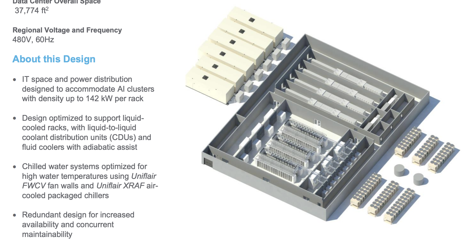
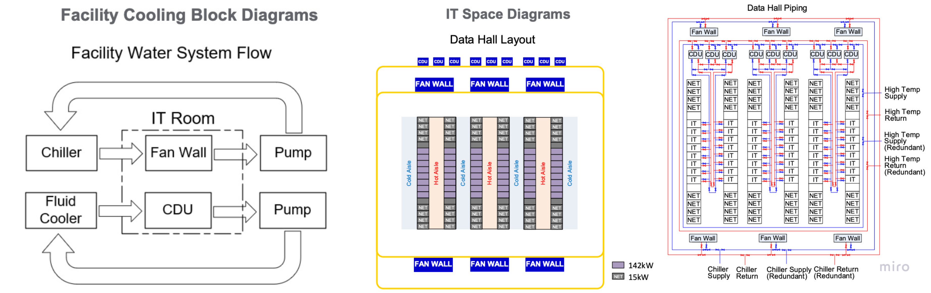
- Chilled-water loop — feeds residual air-cooled equipment (fan walls for racks still partially air-cooled, or front-of-room air handling).
- Warm-water loop — feeds the liquid cold plates at ~40 °C, returning at higher temperature, with the CDU transferring heat into the facility water loop entering the CDU at ~37 °C.
This split lets the datacenter still serve mixed-cooling workloads without forcing the entire facility onto a single temperature envelope. Even with VR NVL72's 100% liquid-cooled trays, the rest of the datacenter (storage racks, network racks, support equipment) still needs air cooling.
Chiller-less — feasible but not universal
- Where it works: in climates where ambient wet-bulb temperature is reliably below ~30 °C, dry coolers or adiabatic towers can reject heat from a 45 °C coolant loop without mechanical compression. Firmus already operates GB200 systems this way.
- Where it doesn't: hot or humid climates where ambient approaches the coolant temperature too closely. There, chillers remain in the loop.
- The economic shift: air-cooled chillers cost roughly $0.5M / MW of cooling capacity; dry coolers / adiabatic towers cost about $0.2M / MW. So chiller-less designs are meaningfully cheaper if your climate allows it.
- Suppliers gaining: SPX Technologies, BAC (Baltimore Aircoil), Evapco on the dry-cooler / tower side. Suppliers losing share: Johnson Controls, Carrier, Trane on the chiller side — though they retain volume for hybrid and mixed-workload datacenters.
The picture is not binary. Most operators will still retain some conventional chiller capacity for flexibility, redundancy, and mixed workload support. However, the long-term direction is clear: as AI-optimized datacenters move toward direct liquid cooling and higher-temperature heat rejection loops, traditional chiller-based cooling capacity becomes less central and gradually gets squeezed.
Where to Read What — Series Map
| Part | Title | Scope |
|---|---|---|
| 1 | Platform Framing & Architecture Map | Blackwell → Rubin platform thesis, headline specs |
| 2 | Rubin GPU — Engineering Deep Dive | Process node, SMs, HBM4, NVLink-C2C, package, CPX + Groq 3 LPX |
| 3 | Vera CPU & the Networking Silicon Family | Vera CPU, NVLink 6 Switch, ConnectX-9, BlueField-4, Spectrum-6 |
| 4 | Rack Assembly — Trays, PCB, and Cooling (this part) | HGX vs NVL72, compute tray modules, cableless midplane, PCB upgrade, liquid cooling |
| 5 | Rack Power and the Networking Fabric | Power delivery, HVDC, tray↔rack wiring, scale-up NVLink 6, scale-out InfiniBand + Ethernet |
| 6 | Supply Chain — Master Reference | Suppliers by subsystem across the entire stack |